
Introduction#
If you haven’t already read Part 1: Equipment I highly recommend it! If you have already read it, or are paying attention to the image above, you should go back and check out some of the edits I’ve released. Most specifically, I’ve finally had a chance to test the AMD RX 580s manufactured into cards by MSI and I can’t say that I recommend them. I anticipated them being better performing mining GPUs, but so far, in all of my tests, it’s just too soon to come to that conclusion. On the other hand, I’ve had fantastic success with MSI Gaming RX 480s.

If you’re confident in your computer assembly skills, you can simply breeze through this part and jump to Part 3: GPU Installation, BIOS Config and First Boot.
Getting everything ready#
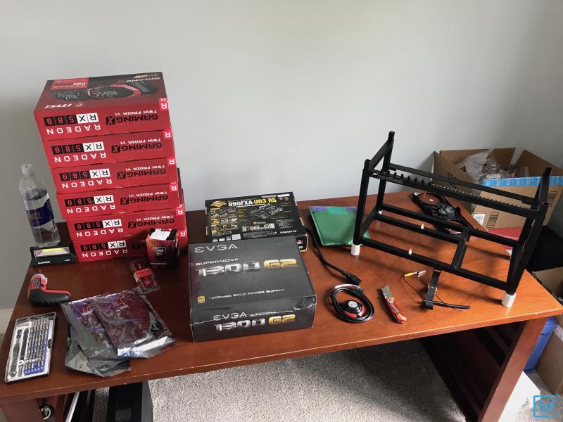
Here is a recap list of all the items that we’ll need to build a 6-GPU rig:
- Motherboard: GA-990FXA-UD3
- CPU: AMD FX4300
- Memory: Kingston HyperX FURY 4GB 1600MHz DDR3
- Power Supply: EVGA SuperNOVA 1300 G2
- GPU Risers (purchase 6 or 8 to have spares): Custom Built
- GPUs (purchase 6 for max stable capacity): RX 480 or RX 580
- Power Button: It looks a bit cheesy, but in person, it’s actually really awesome. A luxury, but worth it
- Rig case (optional): gpushack.com makes the best one I’ve tested
- SSD w/ ethOS: ethOS 32GB SSD
You should have been able to secure all of the above components for less than $1,900. Unfortunately, sourcing parts is quite a challenge, and there are always trade-offs for price and availability.
For tools that you should have on hand, I recommend the following having a Phillips-head screwdriver on hand as well as an anti-static wrist strap to help protect the more sensitive components during assembly.

The wrist-strap simply allows you to remain grounded while handling the electronic components to prevent stray static electricity from causing any damage.
Fitting Power Supply#
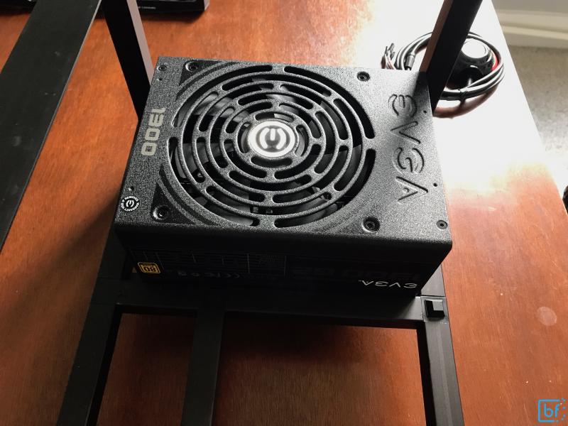
The power supply of a mining rig is arguably one of the most important pieces. I can’t say enough good things about EVGA power supplies, specifically the EVGA SuperNOVA 1300 G2. This power supply automatically floats up to 240v or down to 110v based on the source power. This greatly simplifies building and deploying rigs. In the US, typical home power outlets are on a circuit serving 15-20Amps at 110V. In a perfect world, this allows us access to roughly 1,650 Watts of continuous power. This power supply is capable of drawing 1,300 Watts which means if you want to run more than 1 rig in your farm, you’ll need to spread your rigs across multiple circuits (ensuring proper fire safety) or put them on 240V service which is much more efficient on high power draw applications like rigs/servers. This allows us to use lower amperage service and ultimately lower heat/resistance on the circuit (which equates to higher energy efficiency). The point of all this is that many power supplies only support a specific voltage service or require a manual switch to be flipped to move from 110V to 208-240V. This is a stress we don’t need to add to our operation because it creates both a fire hazard and a high potential of a fatigued decision or fat-fingered mistake blowing up our hard work.
Bottom Line use a high quality power supply.
The folks over at GPU Shack have made an amazingly high quality, effective open-air case that fits this Power Supply beautifully
Fitting the Mother Board#
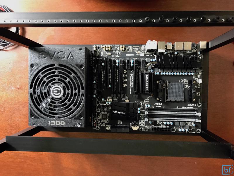
The GPU Shack case that we’re using already comes with tool-less ATX motherboard standoffs. This allows us to quickly and easily fit our GA-990FXA-UD3 Motherboard. Press the motherboard down until the two clips fully engage.
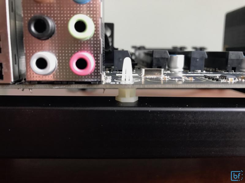
The case uses high-quality rubber stand-offs for the other corners of the motherboard to keep it out of contact with the bottom metal of the case. This is a recent improvement by GPU Shack. They use to include plastic bumpers but in my experimentation, these melted at high temps. However, these new black, rubber bumpers handle the higher operating temperatures with ease.
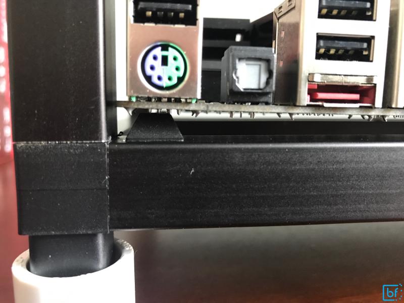
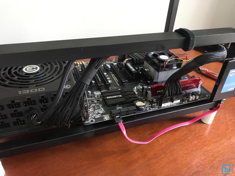
The final fit with motherboard and power supply should look like the following. Note the direction I’ve mounted both. I’ve found this to be the optimal orientation.
Fitting the CPU and Heatsink#
The motherboard that I’ve chosen to use has an AM3+ processor socket. This is a generally familiar experience for those who have fitted AMD processors before, however, if you only have experience with Intel socket types and processors, I recommend you pay close attention as this is a very different locking mechanism!
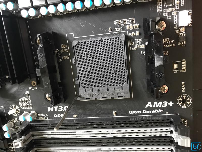
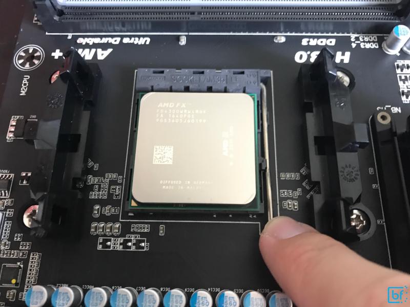
Motherboards with AM3+ sockets are shipped with the socket lever in the locked position. You’ll need to lift this lever to unlock it as indicated in the figure above.
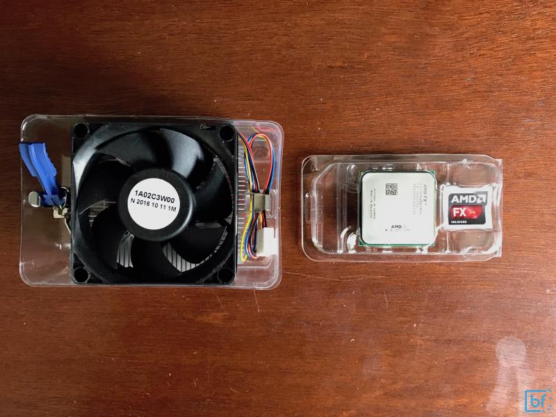
Unboxing the AMD FX4300 will reveal two main components, the actual CPU itself as well as the standard OEM heatsink. This OEM heatsink will be fine for our needs as this tutorial won’t be covering CPU mining, only GPU mining.
We’ll first fit the CPU (ensuring we have our wrist-strap properly secured on both a ground and our wrist) taking careful consideration of the 4 key holes and the gold triangle key mark on the processor and matching indented triangle key mark on the processor socket.
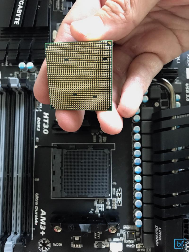
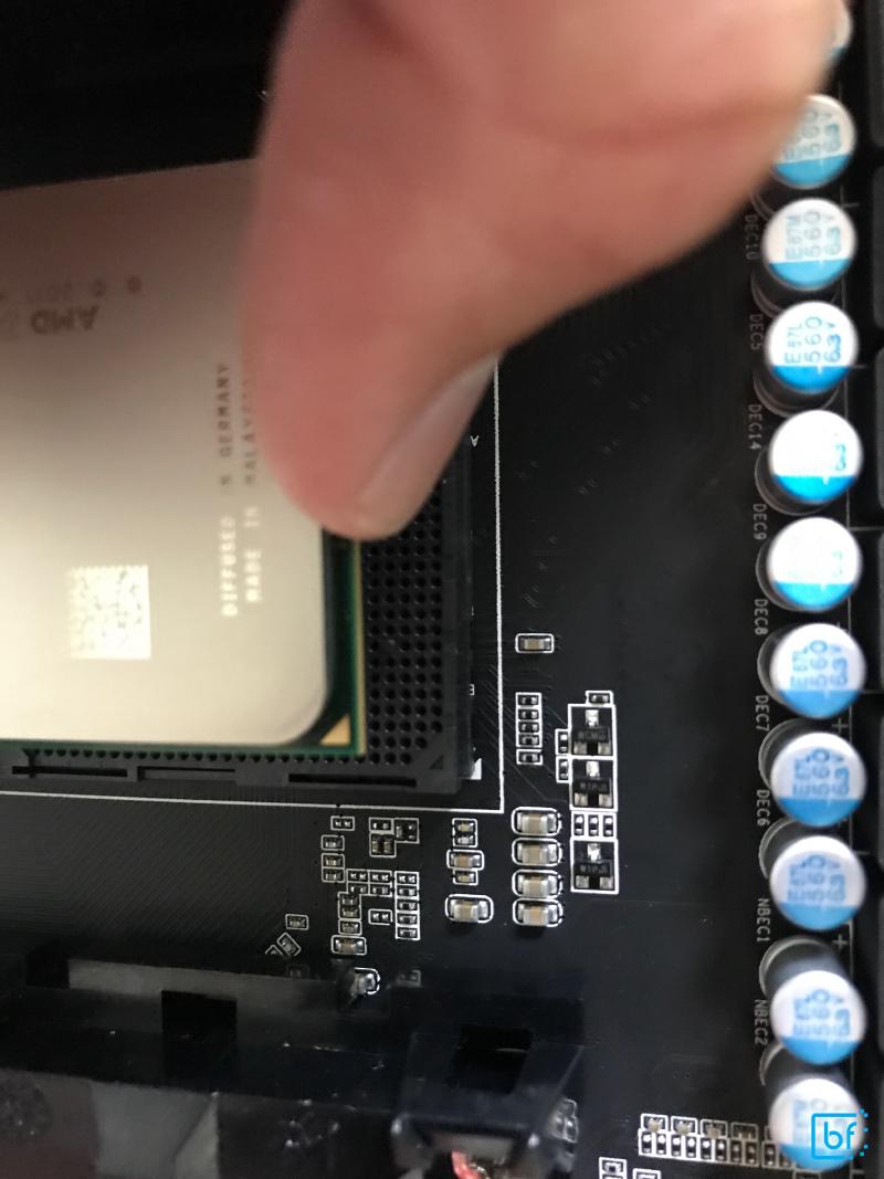
The processor should easily slip into place without force. It will not clip or provide any other feedback of fit other than there being no gap between the processor mount board and the socket.
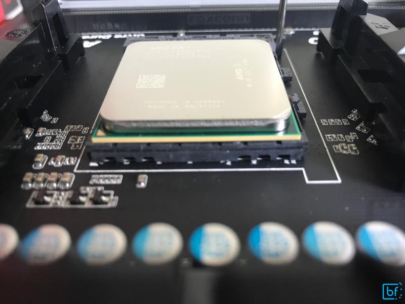
Once we’ve ensured there are no gaps, we’ll secure the lever and the processor will be locked in place.
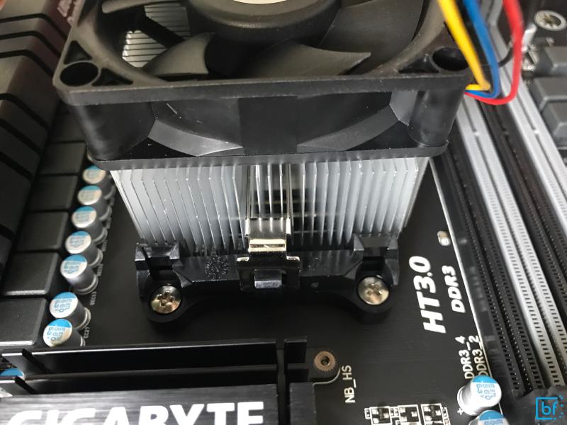
Now we’ll fit the heatsink on top of the CPU and secure it to the mounts on the motherboard. The OEM heatsink will come with thermal paste pre-applied to the bottom (flat part) of the heatsink. Make sure to not touch or rub this against anything. If you do, you may need to secure some additional thermal paste, wipe the existing paste off and re-apply.
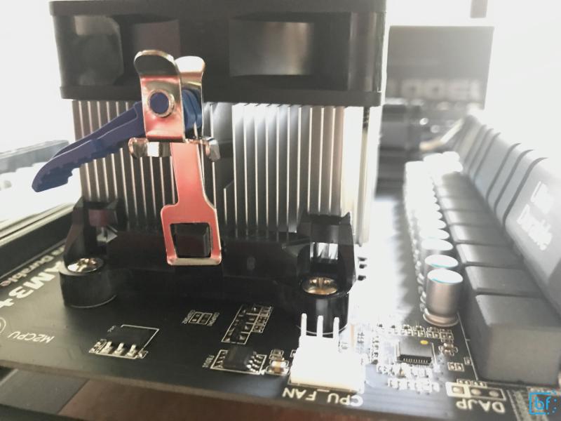
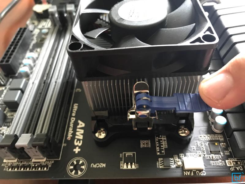
Note that the heatsink will only fit in one direction. Additionally, note the unlocked position of the blue lever and the fact that it’s on the side of the socket closest to the CPU Fan pin-out on the motherboard. There will be two places where the metal securing strap on the heatsink will fit around the on-board mounting. Make sure these are properly fitted, then engage the blue thumb-lever to secure the heatsink into place.
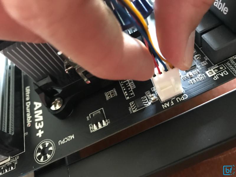
Now we’ll connect the heatsink fan to the on-board fan power controller. Ensure that the connector keying matches up correctly. There is only one way to plug this in.
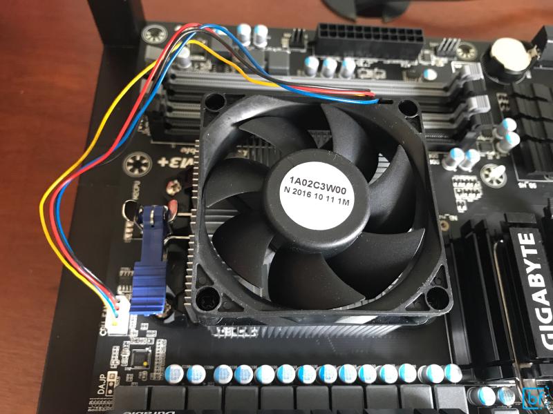
Once we’ve plugged the fan into the board, we’ve completed the CPU installation! It should look like the following figure. You’ll need to ensure that the CPU fan cord does not get in the way or interfere with the fan’s operation.
Memory Installation#
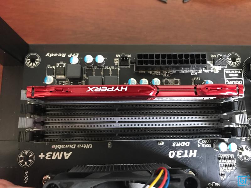
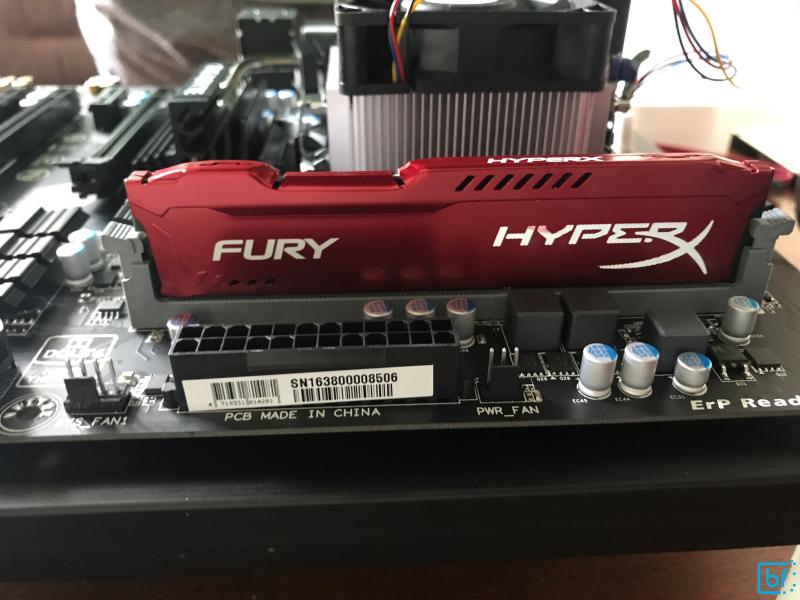
Now that our CPU is installed, we’ll proceed to installing our memory. This is a very simple installation process and is merely a matter of lining up the keyed memory and installing in the correct slot. I’m only using a single Kingston HyperX FURY 4GB 1600MHz DDR3 memory stick because I don’t care too much about high performance on-board memory, just good performance, reliable memory. Since I’m installing a single memory stick into a motherboard that has dual-channel memory, I’m only going to install it in the memory position marked DDR3_1. For this board, it’s the light-gray slot furthest away from the CPU. Refer to the motherboard instruction manual for other memory installation configurations for more than a single stick.
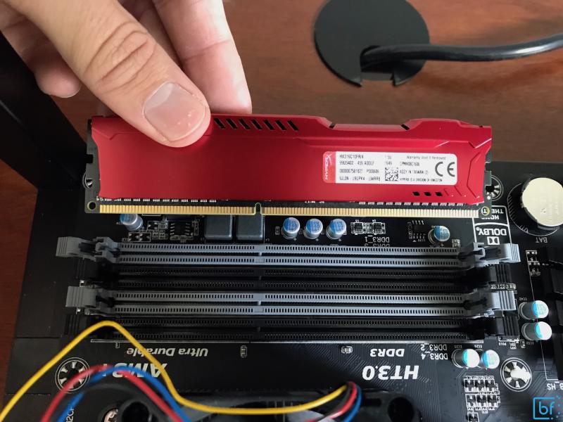
Take note that I’ve lined the memory key hole with the key spot on the slot and I’ve unlatched the on-board memory latches. These latches will automatically lock back when the memory is depressed into the slot. It will take may take a little bit of gentle force.
Connecting the GPU Shack ethOS SSD via SATA#
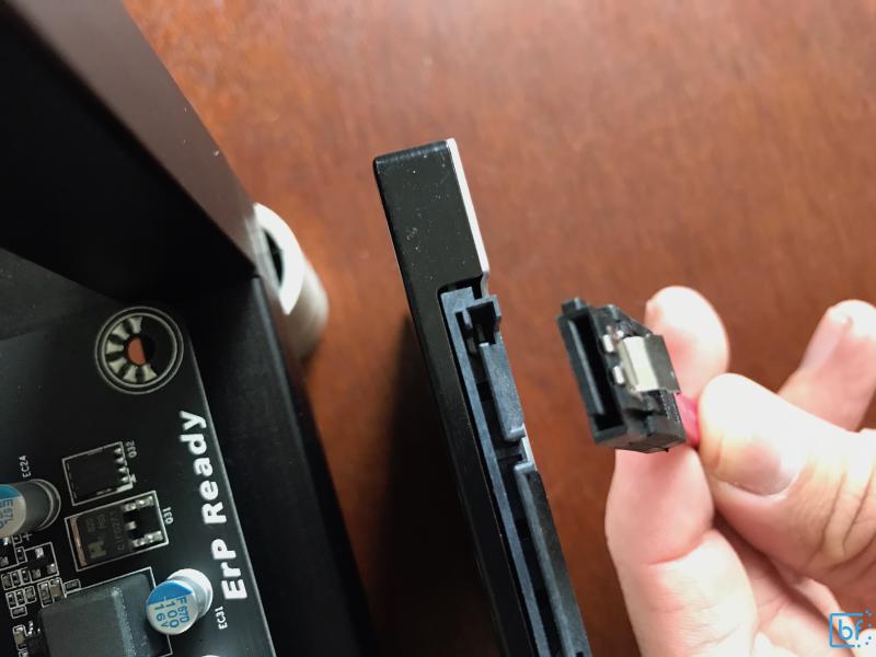
GPU Shack, the distributor of ethOS licenses, sells a pre-installed SSD that I recommended in my product list. This reduces the complexity and time-required to provision the OS for the rig. We’ll connect it via the provided SATA cable to the motherboard and stick use some double-sided tape to secure it to the rig frame.
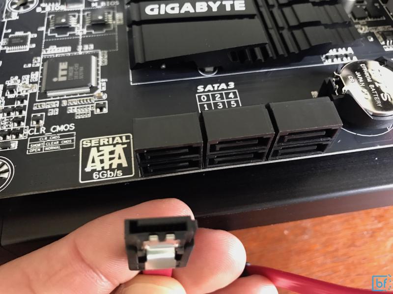
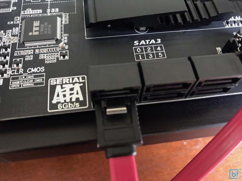
Note that like all cables in computer assembly, the SATA cable is keyed. Pay attention to the keying before attempting to apply force. Since we’re only installing a single SATA drive on to our motherboard, it doesn’t particularly matter which SATA port we use. I’m using SATA3 1 for my connection. The OEM BIOS for the motherboard is smart enough to choose the first boot-able interface as the safe default.
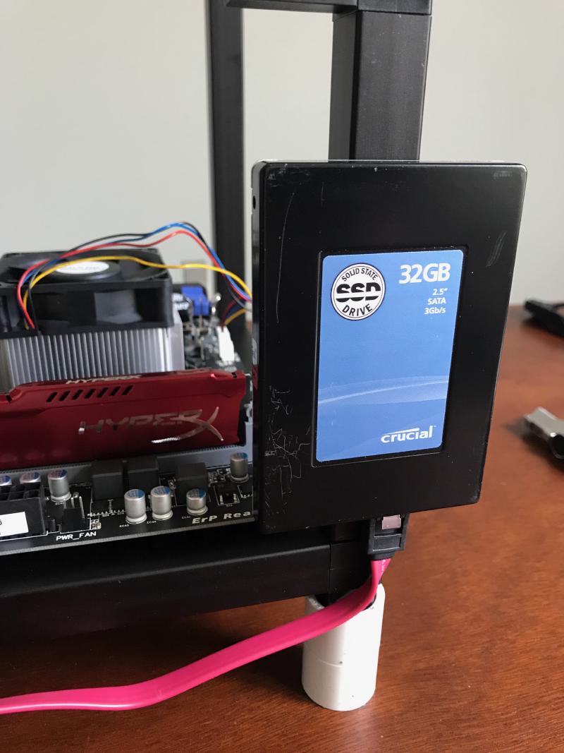
Once connected, we can use double-sided tape to secure the drive to the rig frame (I used a 3M Command Strip).
Connecting the Power Supply to the Motherboard#
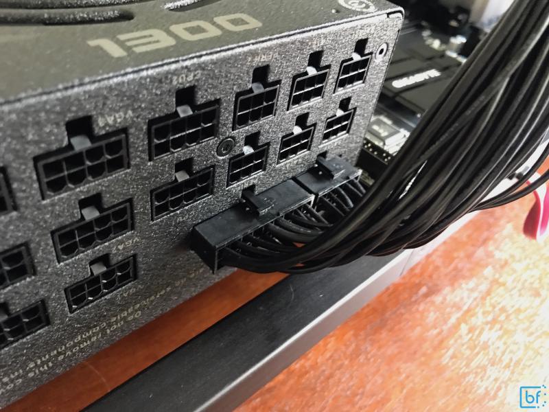
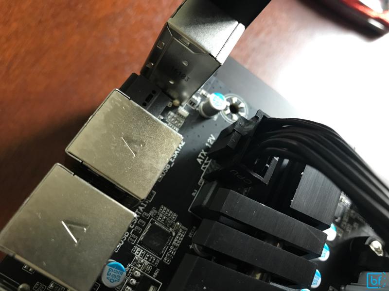
The motherboard will require two main power supply connections. One 8-pin dedicated for the CPU and one 24-pin for the remaining on-board components. These are essentially our main computer arteries, so we’ll want to install them and secure them to prevent too much airflow restriction. Because I’m using a fully modular power supply, I can pick and choose which cables I’ll engage as opposed to being forced to use what’s sticking out the back of the power supply.
We’ll start by connecting the 24-pin cable to the power supply side.
Then connect the other side of the cable to the motherboard.
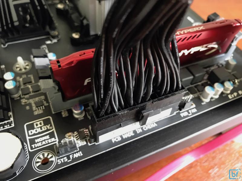
This will be a snug fit, and each power cable will have securing clips on them. Ensure that these clips fully engage to prevent cables from coming unplugged during operation. We’ll also want to secure this cable since it’s rather large. EVGA includes some nice Velcro straps to achieve this.
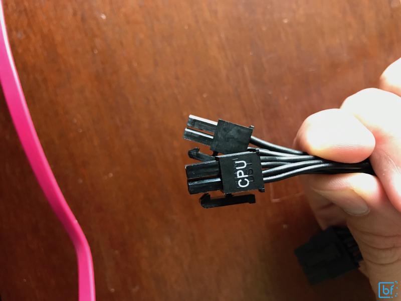
Now the second main power cable, the CPU cable. The motherboard side of this cable often has two separated parts in order to maintain high compatibility with lower-power, 4-pin CPUs. Take note of how these two parts mechanically come together to simulate a single plug so that you can ensure a proper connection.
Once again, make sure that the clips actually clip into place for a confident connection.
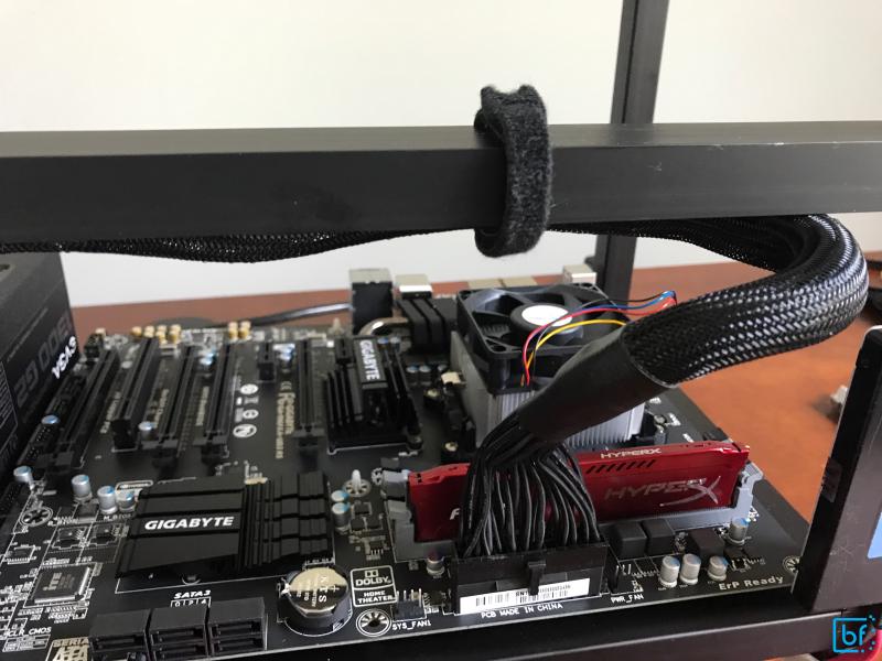
We can add this cable to our main motherboard power cable management strap. The result should be clean looking and allow for maximum airflow.
Fancy Pants Power Switch#
In the hardware sourcing list, I included a link to a pretty awesome (IMO) power switch. You certainly do not need a power switch. It just makes the interface more friendly and having LEDs to indicate drive activity helps a lot when debugging whether or not the machine is hung when it boots or if it’s still doing work. Not to mention, it eliminates shaking hands and a paper clip short from connecting the wrong pins and invoking the wrong function! Motherboards all have similar pin interfaces for power, reset, and LED indicators for power and drive activity. The switch I’ve sourced allows us to use all of these features of the motherboard and includes a long, easily flexible cable to make mounting simple when scaling up the farm.
Extensible Ponderings: I’m considering making some changes to this in the future for some smart remote management with a side-kick micro controller to help bail the rigs out of otherwise dead-in-the-water states. This consideration is competing with a script for remote monitoring and management of my PDUs.
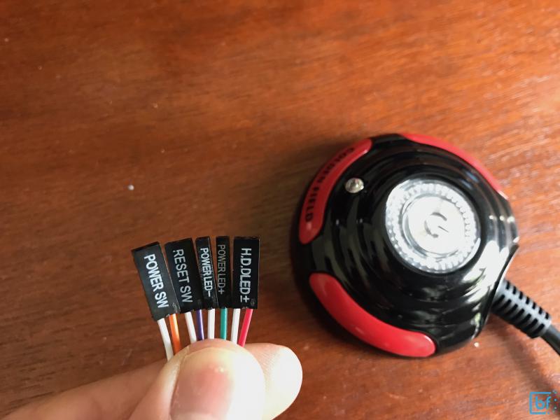
Each of the power button connectors is nicely labeled. Likewise, the motherboards pins are color-coded and labeled for easy reference
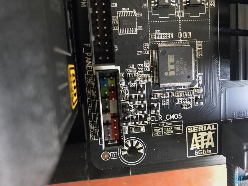
Note: the pins indicate positive and negative polarity for the interface. For the switches, the polarity doesn’t matter to us. However, for the LEDs, the polarity most certainly does matter. Ensure you match the
+with the+and the-with the-for proper function
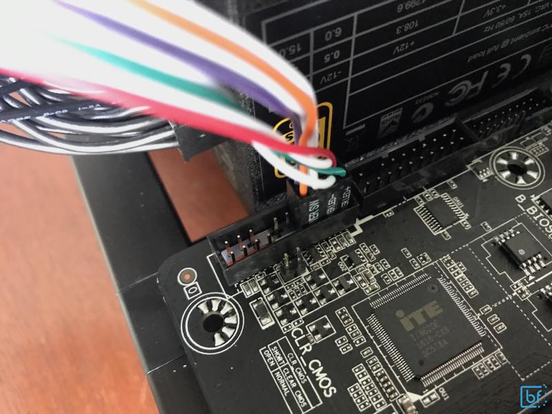
With these easy labels, we can plug everything up making sure to match polarity and function
Moving on to the GPUs#
Now that we have our base fully assembled with a Power Supply, Motherboard, Processor, Memory, SSD, power button and we’re ready to move on to the more specialized install, the GPUs. We’ll cover this in Part 3: GPU Installation, BIOS Config and First Boot.